THE CONTROL SYSTEM OF THE SIAM PHOTON SOURCE
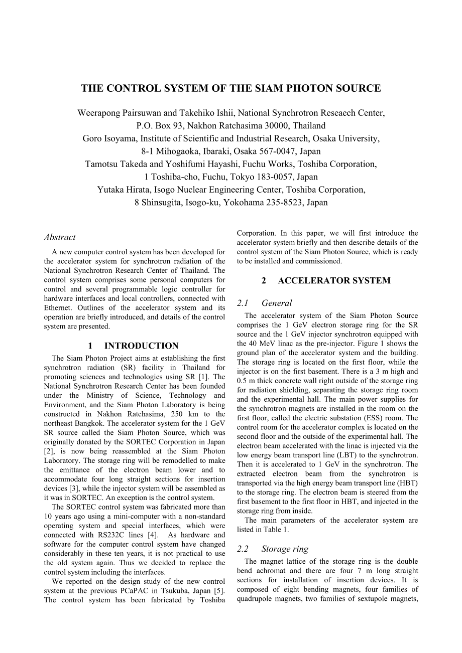
THE CONTROL SYSTEM OF THE SIAM PHOTON SOURCE Weerapong Pairsuwan and Takehiko Ishii, National Synchrotron Reseaech Center, P.O. Box 93, Nakhon Ratchasima 30000, Thailand Goro Isoyama, Institute of Scientific and Industrial Research, Osaka University, 8-1 Mihogaoka, Ibaraki, Osaka 567-0047, JapanTamotsu Takeda and Yoshifumi Hayashi, Fuchu Works, Toshiba Corporation, 1 Toshiba-cho, Fuchu, Tokyo 183-0057, JapanYutaka Hirata, Isogo Nuclear Engineering Center, Toshiba Corporation, 8 Shinsugita, Isogo-ku, Yokohama 235-8523, JapanAbstractA new computer control system has been developed for the accelerator system for synchrotron radiation of the National Synchrotron Research Center of Thailand. The control system comprises some personal computers for control and several programmable logic controller for hardware interfaces and local controllers, connected with Ethernet. Outlines of the accelerator system and its operation are briefly introduced, and details of the control system are presented.1INTRODUCTIONThe Siam Photon Project aims at establishing the first synchrotron radiation (SR) facility in Thailand for promoting sciences and technologies using SR 1. The National Synchrotron Research Center has been founded under the Ministry of Science, Technology and Environment, and the Siam Photon Laboratory is being constructed in Nakhon Ratchasima, 250 km to the northeast Bangkok. The accelerator system for the 1 GeV SR source called the Siam Photon Source, which was originally donated by the SORTEC Corporation in Japan 2, is now being reassembled at the Siam Photon Laboratory. The storage ring will be remodelled to make the emittance of the electron beam lower and to accommodate four long straight sections for insertion devices 3, while the injector system will be assembled as it was in SORTEC. An exception is the control system.The SORTEC control system was fabricated more than 10 years ago using a mini-computer with a non-standard operating system and special interfaces, which were connected with RS232C lines 4. As hardware and software for the computer control system have changed considerably in these ten years, it is not practical to use the old system again. Thus we decided to replace the control system including the interfaces.We reported on the design study of the new control system at the previous PCaPAC in Tsukuba, Japan 5. The control system has been fabricated by Toshiba Corporation. In this paper, we will first introduce the accelerator system briefly and then describe details of the control system of the Siam Photon Source, which is ready to be installed and commissioned.2ACCELERATOR SYSTEM2.1 GeneralThe accelerator system of the Siam Photon Source comprises the 1 GeV electron storage ring for the SR source and the 1 GeV injector synchrotron equipped with the 40 MeV linac as the pre-injector. Figure 1 shows the ground plan of the accelerator system and the building. The storage ring is located on the first floor, while the injector is on the first basement. There is a 3 m high and 0.5 m thick concrete wall right outside of the storage ring for radiation shielding, separating the storage ring room and the experimental hall. The main power supplies for the synchrotron magnets are installed in the room on the first floor, called the electric substation (ESS) room. The control room for the accelerator complex is located on the second floor and the outside of the experimental hall. The electron beam accelerated with the linac is injected via the low energy beam transport line (LBT) to the synchrotron. Then it is accelerated to 1 GeV in the synchrotron. The extracted electron beam from the synchrotron is transported via the high energy beam transport line (HBT) to the storage ring. The electron beam is steered from the first basement to the first floor in HBT, and injected in the storage ring from inside. The main parameters of the accelerator system are listed in Table 1. 2.2 Storage ringThe magnet lattice of the storage ring is the double bend achromat and there are four 7 m long straight sections for installation of insertion devices. It is composed of eight bending magnets, four families of quadrupole magnets, two families of sextupole magnets, and horizontal and vertical steering magnets. The bending magnets are connected serially to a single power supply. The bending and the quadrupole magnets have correction coils each. There are an RF acceleration system consisting of an RF cavity, an RF amplifier and a low level controller, and an injection system consisting of a septum magnet and three perturbator magnets. Some monitors and diagnostics tools are installed such as a beam current monitor, beam position monitors, vacuum gauges, and an RF knockout system.2.3 InjectorThe injector is composed of the linac, the synchrotron, LBT, and HBT. The linac has its hardware control system in the control room and it is possible to remotely operate the linac by exchanging some commands and status only. There are two bending magnets, eleven quadrupole magnets in LBT. Three screen monitors, vacuum gauges, two slits for scraping the electron beam, and some monitors are also installed.In the synchrotron, there are 12 bending magnets and two families of quadrupole magnets. These magnets are excited by the large power supplies B, QF and QD in the ESS room. Excitation patterns of these magnets are given in the pattern memories for the power supplies. There are several horizontal and vertical steering magnets, and an RF accelerator system in the synchrotron. Some monitors and diagnostics tools are also provided. A septum magnets and 4 perturbator magnets are used for injection, and a fast kicker magnet and a septum magnet are used for extraction of the electron beam.HBT comprises of two vertical bending magnets, two horizontal bending magnets, eight quadrupole magnets, and some horizontal and vertical steering magnets. Monitors installed are some screen monitors, vacuum gauges and beam current monitors.2.4OperationAt present it is expected that the accelerator system will be operated only in the daytime and the evening. The daily operation of the accelerator system will be made as follows. It will be started up in the morning and the beam will be injected in the storage ring. It will take several minutes to fill electrons in the storage ring. After electrons being filled in the storage ring, the operation mode of the storage ring will be changed for user experiments; the closed orbit may be corrected, the undulator gap will be changed. The injector will be set to the standby mode for a next injection. The electron beam in the storage ring will decay in several hours. This operation will be repeated a few times a day in the routine operation for user experiments. Then the accelerator system is shut down in the evening.3NEW CONTROL SYSTEMThere are several requirements for the new control system; it should provide an easy tool for routine operation for user experiments, and special and detailed operation of every device under control should be possible in machine study. The control system should be flexible for future extension not only of the accelerator system but also of the control system itself. The hardware including computers and interfaces will become old-fashioned quickly, so that it should be possible to replace Table 1: Main parameters of the accelerator complexLinacEnergy40 MeVRF frequency2.856 GHzBeam current60-80 mAMacropule width1.7 sEnergy spread (FWHM)1.3 %Emittance0.7 m radSynchrotronEnergy1.0 GeVCircumference43.19 mBeam current30 mARepetition rate1.25 HzRF frequency118 MHzHarmonic number7Storage ringEnergy1.0 GeVCircumference81.3 mStored current (expected)500 mAMagnet latticeDBASuperperiodicity4Long straight sections7 m4Natural emittance74 nm radRF frequency118 MHzHarmonic number16Figure 1: Ground plan of the accelerator system and the building. ycrt oEprmntal HallStorage RingHigh Energy BeamTransport LneLow Energy BeamTransport LineInjector LinacElectricSubstationControl Roomit with new one without changing control software. Considering these factors, we have decided to adopt a combination of personal computers (PC) for control computers and programmable logic controller (PLC) for interfaces for the new control system of the accelerator complex. The characteristics of the control system are as follows; (i) it is a distributed control system, (ii) only general purpose components such as PCs and PLCs are used, (iii) consequently it is easy to upgrade and expand, (iv) it is reliable since control of devices are mainly conducted by PLCs, and (v) it is cost effective.4HARDWARE4.1System StructureThe schematic diagram of hardware of the control system is shown in Fig. 2. The control system consists of two PCs for control, which we called servers, three PCs for operator terminals, and five device control stations (DCS), each of which has a PLC inside for interfaces. There is an additional DCS with a PLC named global interlock system (GIS), which is the interlock system for radiation safety. These PCs and PLCs are connected with Ethernet via a switching HUB in the control room. The PCs and the PLCs in the control room are connected with hard wires. The other PLCs in the synchrotron, the electric substation and the storage rooms are connected with optical cables. A router is also connected to the HUB and the control system is linked with LAN in the laboratory. It is possible to access only the database server (ACQ-SRV) from outside. The control server (CNT-SRV) is connected with GPIB or RS232C interface to the pattern memory defining excitation patterns of the main magnets in the synchrotron, a digital multi-meter for the stored beam current in the storage ring, and the timing controller for injection and extraction of the electron beam and so on.4.2InterfacesThe five DCSs are branches of the control system and they work as local controllers as well as interfaces. Each contains a 16-port HUB for connection to the network, a PLC, and input and output (I/O) terminals for controlled devices. LBT-DCS and SYN-DCS are installed in the synchrotron room, ESS-DCS in the electric substation room, STR-DCS in the storage ring room, and CNT-DCS together with GIS in the control room. LBT-DCS consists of two racks, while STR-DCS is separated to two components; one consists of three racks and the other two racks. The other DCSs have a single rack. CNT-DCS and GIS in the control room are assembled in a single rack.We adopted PLCs made by Rockwell Automation / Allen Bradley named ControlLogix, since it is widely Figure2: Structure of the control system.Control RoomEthernet (OpticalCable)DataLoggerPatternMemoryDigitalMulti-meterTS-1TS-2ModemServer DeskIBM 互換機IBM 37XXCNT-SRVIBM 互換機IBM 37XXACQ-SRVDevices in CNTDevices in GISGIS-DCSCNT-DCSGPIBRS-232CHUBOperator DeskPrinterOPR-PC1OPR-PC2OPR-PC3LANLANLocalRouterSTR RoomDevices in STR & HBTSTR-DCSESS RoomDevices in ESSESS-DCSSYN RoomDevices in LBT & LinacDevices in SYNLBT-DCSSYN-DCSModemRS-232CEthernet (100BASE-T)RS232C (Optical Cable)accepted as the defacto standard and good maintenance service is available in Thailand. A standard PLC comprises a CPU module with 2 MB user memories, an Ethernet module, I/O modules, and some 17-slot chassis. In order to reduce a CPU load, two CPU modules are used in STR-DCS, to which many controlled devices are connected compared with the others. Chassis in a DCS are connected each other with a special LAN provided for the PLC system, named ControlNET. The I/O modules used in the DCSs are 6-point isolated analogue input (voltage or current) modules, 16-bit isolated digital input (DC 24 V) modules, 32-bit digital input (DC 24 V) modules, 16-bit digital output (DC 24 V) modules, and 8-point isolated relay modules.4.3Control ComputersWe adopted PCs made by Compaq, because the maker guarantees to use both Japanese and English operating systems, they are purchasable in Japan, and the reliable maintenance system is established in Thailand. The server PCs are Compaq ProLiant ML370 (Pentium III 667 MHz, 17 inch CRT, 512 MB memories, 18.2 GB HDD 2). Two hard disks in a sever PC constitute RAID 1 for mirroring. Each server PC has both GPIB and RS232C interfaces and in case one of them goes wrong, the control system can work with the remaining one. These server PCs are connected to an uninterruptible power supply (UPS). The operator terminals are Deskpro WS 250 (Pentium III 866 MHz, 19 inch CRT, 256 MB memories, 20 GB HDD) The operating system of these PCs is Windows NT 4.0.5SOFTWARE5.1Control Software in PLCsA PLC operates and monitors the devices under control. Operation of a power supply is performed typically as follows. The first example is power on; (i) status check before operation, (ii) operation of power on by a pulsed signal, (iii) confirmation of the status to change to power-on within a prefixed time. The second example is setting of the output current, (i) conversion of a numerical value, (ii) status check before operation, (iii) setting of an output Figure 3: Example of control panels on the operator PC. current, (iv) output of a strobe with 20 ms duration. The program for control is written in the standard ladder language for PLC. The PLCs execute two kinds of jobs in parallel; one is consecutive loops and the other is interruptions in every 20 ms.Communications with the upper level controllers take place via registers in the PLCs. When an operator PC orders operation to a device, the PC writes a command in a register of a PLC through Ethernet. The PLC reads the command and executes it. It continuously reads status of the devices and writes in registers, so that the control PCs can obtain practically real-time information about the devices by reading the registers.A special function is provided, which enables to vary the output current of a power supply continuously or synchronously with other power supplies. This function will be used to accelerate the electron beam in the storage ring or to excite a super-conducting wiggler with the operation point kept constant in the tune diagram. A PLC has a set of 100 registers for one numerical setting. If you write a initial value, a final value and an interval in the registers, the PLC interpolates linearly between these two values and set the value in between to a power supply at every 100 ms. Since 100 such values can be specified, any output variations which is a non-linear function of time can be approximated with a line graph.5.2Control Software in PCsSince practical control of individual devices is conducted by the PLCs, the main role of the operator PCs is to provide the man-machine interface for control. Operation of individual devices and reading status from them are made by directly writing commands in registers of the PLCs and reading status or numerical values from them via Ethernet. Exceptions are the devices connected to CNT-SRV using GPIB or RS232C. How to exchange commands and data between the operator PCs and CNT-SRV depends on devices. Some data is transferred using a data file in CNT-SRV and others via PLCs. Automatic operation of the accelerator system, which was be mentioned in Chapter 2, is conducted by the PLC in CNT-DCS. The procedure for automatic operation is programmed in the PLC and an operator PC only triggers it.There are three sorts of control program running in the operator PCs; automatic operation, individual control, and monitors and utilities. Automatic operation is used for routine operation of the accelerator system, such as start-up or shut-down. The accelerator system can be automatically operated by a single click of a button. Individual control is used for display of operational status of the devices under control and for fine adjustment, which will be mainly used in machine study. Monitors and utilities are programs used for measurements and displays of the beam current, vacuum, beam positions in the storage ring, setting of excitation patters of the main magnets of the synchrotron, and so on.Two kinds of man-machine interfaces are provided for individual operation; one is a table format, with which a choice and operation of a device can be quickly made, and the other is a graphical user interface showing schematic drawing of the accelerator system. Either one can be chosen depending on the purpose. An example of the control windows on an operator PC is shown in Fig. 3.These man-machine interfaces are written with Visual Basic for Applications and RS View 32 of the Rockwell Software. An operator PC reads only data displayed on the screen from PLCs. The interval to read input data on a window and to write them in PLCs, or read status from PLCs can be independently set to each operator PC and the interruption time is now set at 0.3 s. If the response time is defined as the time between start of operation and the change of status due to the operation, twice the interruption time is the minimum response time of the control system. In the practical use, we plan to adjust the renewal time of the man-machine interface windows in order to optimise the response time and the network load.6PRESENT STATUS AND PLANS The control system was completed and inspected for acceptance at the Fuchu Works of Toshiba Corporation at the beginning of September 2000. Installation of the new control system will be commenced in January 2001, when re-assembling of the accelerator system will be in the final stage. Commissioning of the control system will be completed in a few months. We have plans to install an undulator in a few years and a super-conducting wiggle in the next phase, and accordingly the control system will be upgraded progressively. REFERENCES1 W. Pairsuwan and T. Ishii, “The Siam Photon Project”, Proc. of APAC 98, KEK, Tsukuba, Japan, March 1998, p. 36.2 M. Kodaira, N. Awaji, T. Kishimoto, H. Usami, and M. Watanabe, “Development of Highly Stable Synchrotron Radiation Source at SORTEC”, Jpn. J. Appl. Phys. 30 (1991) 3043.3 P. Kengkan, W. Pairsuwan, G. Isoyama, T. Yamakawa and T. Ishii, “Magnet Lattice for the Siam Photon Source”, J. Synchrotron Rad. 5 (1998) 348.4 M. Takanaka, T. Iida, A. Komine, N. Awaji, S. Nakamura, M. Ohno and E. Toyoda, “Control System of the 1 GeV Synchrotron Radiation Source at SORTEC”, Proc. EPAC 90, 1990, Vol. 1, p. 836.5 W. Pairsuwan, T. Ishii, G. Isoyama, T. Yamakawa, Y. Hirata, T. Takeda, and N. Tsuzuki, “Computer Control System for the Siam Photon Sourcet”, Proc. of PCaPAC 99, KEK, Tsukuba, Japan, January 1999, Fr5.我的大学我的大学爱爱情情观观1 1、什么是大学、什么是大学爱爱情:情:大学是一个相对宽松,时间自由,自己支配的环境,也正因为这样,培植爱情之花最肥沃的土地。
大学生恋爱一直是大学校园的热门话题,恋爱和学业也就自然成为了大学生在校期间面对的两个主要问题恋爱关系处理得好、正确,健康,可以成为学习和事业的催化剂,使人学习努力、成绩上升;恋爱关系处理的不当,不健康,可能分散精力、浪费时间、情绪波动、成绩下降因此,大学生的恋爱观必须树立在健康之上,并且树立正确的恋爱观是十分有必要的因此我从下面几方面谈谈自己的对大学爱情观2 2、什么是健康的、什么是健康的爱爱情:情:1) 尊重对方,不显示对爱情的占有欲,不把爱情放第一位,不痴情过分;2) 理解对方,互相关心,互相支持,互相鼓励,并以对方的幸福为自己的满足; 3) 是彼此独立的前提下结合;3 3、什么是不健康的、什么是不健康的爱爱情:情:1)盲目的约会,忽视了学业;2)过于痴情,一味地要求对方表露爱的情怀,这种爱情常有病态的夸张;3)缺乏体贴怜爱之心,只表现自己强烈的占有欲;4)偏重于外表的追求;4 4、大学生、大学生处处理两人的在理两人的在爱爱情情观观需需要三思:要三思:1. 不影响学习:大学恋爱可以说是一种必要的经历,学习是大学的基本和主要任务,这两者之间有错综复杂的关系,有的学生因为爱情,过分的忽视了学习,把感情放在第一位;学习的时候就认真的去学,不要去想爱情中的事,谈恋爱的时候用心去谈,也可以交流下学习,互相鼓励,共同进步。
2. 有足够的精力:大学生活,说忙也会很忙,但说轻松也是相对会轻松的!大学生恋爱必须合理安排自身的精力,忙于学习的同时不能因为感情的事情分心,不能在学习期间,放弃学习而去谈感情,把握合理的精力,分配好学习和感情3、有合理的时间;大学时间可以分为学习和生活时间,合理把握好学习时间和生活时间的“度”很重要;学习的时候,不能分配学习时间去安排两人的在一起的事情,应该以学习为第一;生活时间,两人可以相互谈谈恋爱,用心去谈,也可以交流下学习,互相鼓励,共同进步5 5、大学生、大学生对爱对爱情需要情需要认识认识与理解,与理解,主要涉及到以下几个方面:主要涉及到以下几个方面:(1)明明确确学学生生的的主主要要任任务务“放弃时间的人,时间也会放弃他大学时代是吸纳知识、增长才干的时期作为当代大学生,要认识到现在的任务是学习学习做人、学习知识、学习为人民服务的本领在校大学生要集中精力,投入到学习和社会实践中,而不是因把过多的精力、时间用于谈情说爱浪费宝贵的青春年华因此,明确自己的目标,规划自己的学习道路,合理分配好学习和恋爱的地位2) 树树林林正正确确的的恋恋爱爱观观提倡志同道合、有默契、相互喜欢的爱情:在恋人的选择上最重要的条件应该是志同道合,思想品德、事业理想和生活情趣等大体一致。
摆正爱情与学习、事业的关系:大学生应该把学习、事业放在首位,摆正爱情与学习、事业的关系,不能把宝贵的大学时间,锻炼自身的时间都用于谈情说有爱而放松了学习 相互理解、相互信任,是一份责任和奉献爱情是奉献而不时索取,是拥有而不是占有身边的人与事时刻为我们敲响警钟,不再让悲剧重演生命只有一次,不会重来,大学生一定要树立正确的爱情观3) 发发展展健健康康的的恋恋爱爱行行为为 在当今大学校园,情侣成双入对已司空见惯抑制大学生恋爱是不实际的,大学生一定要发展健康的恋爱行为与恋人多谈谈学习与工作,把恋爱行为限制在社会规范内,不致越轨,要使爱情沿着健康的。